
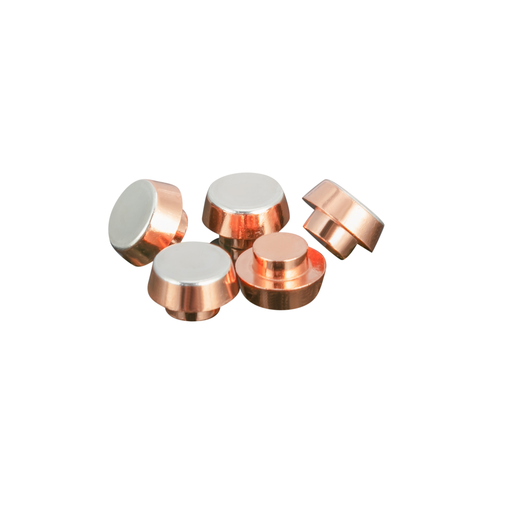
Separate the dominant damage mechanism
Arc erosion removes or redistributes material during opening and closing. Material transfer creates an uneven gain on one contact and loss on the other. Contact welding occurs when local heating and force create a junction strong enough to prevent the pair from separating normally.
Oxide films, contamination, mechanical wear, a loose rivet or weld, and local terminal heating can produce overlapping symptoms. Record both working faces and the attachment before cleaning so the investigation does not lose evidence.
Describe the real electrical duty—not only nominal current
Motors, solenoids, transformers, lamps, capacitors, heaters, and electronic power supplies can create different inrush, recovery voltage, current-zero, and arc-duration conditions. AC and DC switching at the same nominal current are not equivalent.
Capture voltage, steady current, measured or specified inrush, load composition, polarity where relevant, switching frequency, protective components, and the required electrical life. Oscilloscope or current-probe evidence from representative operation is more useful than a nameplate value alone.
Review force, bounce, speed, alignment, and heat removal
Low contact force, excessive bounce, slow opening, poor alignment, or insufficient overtravel can concentrate heating and prolong arcing. A suitable material cannot compensate for a mechanism that does not establish and separate the interface consistently.
Check the current path beyond the working face. Attachment resistance, terminal geometry, conductor size, nearby heat sources, and enclosure temperature can raise the local temperature and change the behaviour of the contact pair.
Screen material families against the failure evidence
AgNi is a common starting family when a balance of conductivity, wear, and manufacturability is needed. AgSnO₂ is often reviewed when welding and arc erosion under demanding loads are central concerns. Fine silver and silver composites can suit controlled low-energy duties, while AgW or AgWC systems may be considered for selected high-arc applications.
AgCdO can remain in established designs where its use is permitted, but substance restrictions and qualified alternatives must be reviewed for the destination market and product. No material family is universally superior; grade, geometry, contact force, attachment, and circuit conditions act together.
Use an evidence loop for corrective action
Compare unused, normally aged, and failed contacts from controlled lots. Document mass or profile loss where practical, resistance and temperature trends, operating count, weld force or separation failure, and high-magnification images of both poles.
Test one controlled change at a time when possible. A new material, changed spring force, faster opening mechanism, snubber, revised geometry, or improved attachment can each affect the result; changing several variables together makes the cause difficult to prove.
- Preserve as-received surface evidence
- Record electrical waveforms and operating count
- Measure force, travel, bounce, and opening speed
- Localize resistance and temperature rise
- Validate corrective action to the required life and environment
Frequently asked questions
Does pitting always mean the contact alloy is wrong?
No. Pitting can also be driven by load waveform, bounce, opening speed, force, alignment, thermal conditions, or attachment problems.
Can a higher contact force prevent welding?
Force is one important variable, but welding also depends on inrush, local heating, bounce, geometry, material, opening dynamics, and circuit protection. The complete system must be evaluated.
Should both contacts be inspected during failure analysis?
Yes. Material loss on one side and buildup on the other, polarity effects, alignment, and asymmetric heating are easier to understand when the mating pair is preserved and documented together.
Discuss your application with SGEI
Send the switching duty, drawing, dimensions, and forecast quantity for a focused engineering review.
Start an RFQ