
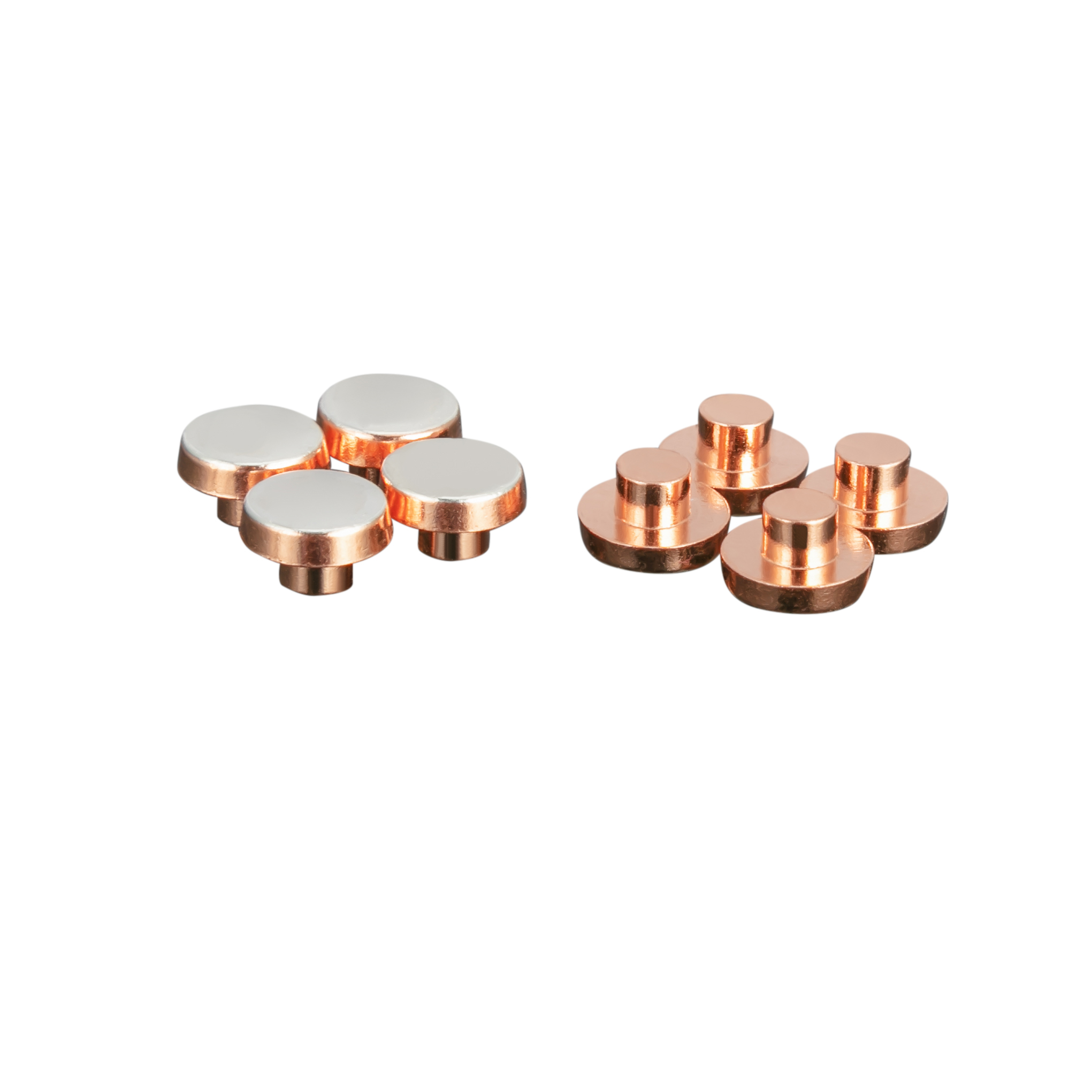
Name every functional dimension
A contact-rivet drawing should identify head diameter (D), shank diameter (d), head or working-head thickness (T), composite working-layer thickness (S), and shank or overall length (L). Define the datum scheme and show exactly where each dimension is measured.
Head profile, spherical radius (SR), edge radii, chamfers, and forming angle (α) influence contact engagement, automated feeding, riveting, alignment, and the final switching gap. Avoid relying on an unlabeled reference sketch when a production dimension is functionally important.
- D — contact-head diameter
- d — shank diameter
- T — head or working-head thickness
- S — functional alloy-layer thickness
- L — shank or overall length
- SR and α — head profile and forming geometry
Control the working layer and material interfaces
For bimetal and trimetal parts, the visible head size does not by itself define the quantity or position of the functional alloy. Specify the working-layer diameter and thickness, the supporting body material, and any third interface or attachment layer required by the construction.
Interface integrity, concentricity, edge exposure, surface defects, and layer continuity should be addressed in the drawing or inspection plan when they affect switching, riveting, thermal flow, or material traceability.
Use catalogue tolerances as a starting reference
The SGEI catalogue cites JB/T 10383-2002 reference values of ±0.05 mm for head diameter D and head thickness T, ±0.03 mm for layer thickness S, +0/-0.05 mm for shank diameter d, and ±0.10 mm for length L. It also shows a spherical-radius reference of 2-3 × D and a forming-angle range of 7-9 degrees.
These values are not automatically correct for every size, process, assembly, inspection method, or application. Put the project-specific tolerance on the controlled drawing and identify whether the catalogue value is accepted, tightened, relaxed, or replaced.
Connect each critical feature to an inspection method
A tolerance is useful only when the measurement method, fixture, sampling plan, and acceptance rule are understood. Define how head and shank diameters are measured, how the working layer is verified, and whether destructive sectioning is required for initial samples or periodic checks.
For automated assembly, include characteristics such as burr direction, straightness, head-to-shank concentricity, surface cleanliness, orientation, and packaging presentation when they affect feeding or riveting even if they are not part of a generic catalogue table.
- Measurement method and calibrated equipment
- First-article and production sampling frequency
- Critical-to-function dimensions and defect limits
- Lot traceability and material documentation
- Packaging and feeding requirements
Release production from an approved sample and revision
Link the approved sample, drawing revision, material specification, and inspection record before production release. If the head profile, layer thickness, alloy, attachment method, or assembly process changes, evaluate whether a new sample approval and switching validation are required.
A clear revision trail prevents a visually similar rivet from being treated as equivalent when its material structure or functional geometry has changed.
Frequently asked questions
Can I quote a contact rivet from overall dimensions only?
An initial estimate may be possible, but a production quotation should define material, construction, head and shank geometry, working-layer dimensions, tolerances, surface requirements, inspection, and quantity.
Are the SGEI catalogue tolerances mandatory for every rivet?
No. They are reference values. The approved project drawing and agreed inspection plan control the finished part.
How is a composite layer normally verified?
The method depends on the construction and requirement. Initial or periodic verification may include controlled sectioning and microscopy in addition to dimensional and visual inspection.
Discuss your application with SGEI
Send the switching duty, drawing, dimensions, and forecast quantity for a focused engineering review.
Start an RFQ